Gates are the fundamental building block of all digital logic circuits. A gate is an electronic circuit that produces an output signal that is a Boolean operation on its input signals. Gates are built from transistors. When an input signal changes the output appears almost instantaneously. There is a small delay, called gate delay, for the signal to propagate through the gate.
The basic gates are AND, OR, and NOT, corresponding to the logical operations. There are three ways to define a gate, and the same three methods can be used to define a digital circuit: truth tables, algebraic notation, and graphic symbols.
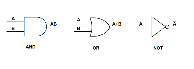
Sometimes NOT is denoted by just a small circle.
For example, given the following truth table:
| A |
B |
F |
|---|---|---|
| 0 | 0 | 0 |
| 0 | 1 | 1 |
| 1 | 0 | 1 |
| 1 | 1 | 1 |
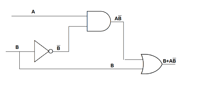
We can construct the algebraic expression AB + AB + AB for the function by looking at inputs for the rows where the value of the function is 1, and ORing those inputs together. We can simplify the expression to B + AB algebraically (try it yourself). The graphic representation of the simplified function is
This example shows how to create a circuit:
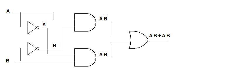
For example, suppose we want to create a circuit for the exclusive OR function, which is true if either input is true, but false if both are true. First we create the following truth table:
| A |
B |
F |
|---|---|---|
| 0 | 0 | 0 |
| 0 | 1 | 1 |
| 1 | 0 | 1 |
| 1 | 1 | 0 |
Next we observe that the truth table represents the algebraic expression AB + AB. We can draw the circuit as follows:
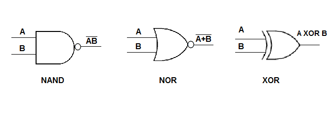
We don't need to use all three types of gates to implement circuits. Usually the types of gates is limited because it's simpler to design and build circuits if only one or two types of gates are used. The additional gates most commonly used are NAND ("NOT AND") and NOR ("NOT OR"), which are defined as follows:
          A NAND B = NOT (A AND B)
                   = AB

          A NOR B  = NOT (A OR B)
                   = A+B
| A |
B |
A NAND B A·B |
A NOR B A+B |
|---|---|---|---|
| 0 | 0 | 1 | 1 |
| 0 | 1 | 1 | 0 |
| 1 | 0 | 1 | 0 |
| 1 | 1 | 0 | 0 |
For gates to be useful we must be able to use them to implement any Boolean function; we call a set of gates that can implement any function a "functionally complete" set of gates. The following are functionally complete sets: {AND, OR, NOT}, {AND, NOT}, {OR, NOT}, {NAND}, {NOR}. The first set is functionally complete because it contains the fundamental operations of Boolean algebra. For each of the other sets, we can prove that it is functionally complete by showing how to implement the fundamental operations (AND, OR, and NOT) using the operations in the set under consideration.
A combinational circuit is an interconnected set of gates whose output at any given time is a function only of the input. Note that this means that there is no memory or storage involved. The output appears almost immediately after the input, subject only to gate delay. In general a combinational circuit has n binary inputs and m binary outputs. Like a gate, a combinational circuit can be represented by a truth table, boolean equations, and graphical symbols.
Combinational circuits include adders, multiplexers (which choose one of a set of inputs based on the value of a control signal), and encoders (which use the inputs to activate one of a set of outputs).
Combinational circuits implement the computation and control functions of a digital computer, but (aside from ROM) they provide no memory, which is also essential. For this we use sequential circuits. In these more complex circuits the current output depends on the inputs and on the current state of the circuit. Sequential circuits include flip-flops, which store 1 bit, registers, and memory.
A half adder adds two single bits and produces two outputs: the sum and the carry.
     0      0      1      1
   + 0    + 1    + 0    + 1
   ---    ---    ---    ---
     0      1      1     10
In the first three cases above the carry is 0. The truth table for the half adder is:
| A |
B |
sum |
carry |
|---|---|---|---|
| 0 | 0 | 0 | 0 |
| 0 | 1 | 1 | 0 |
| 1 | 0 | 1 | 0 |
| 1 | 1 | 0 | 1 |
Note that the carry is AB and the sum is A XOR B. We can implement this with AND and XOR gates as follows:

If we are adding numbers of more than one bit then we also have a carry in from the previous column, giving us a function of 3 inputs and 2 outputs. This is a full adder, given by the following truth table.
| A |
B |
Carry In |
Sum |
Carry Out |
|---|---|---|---|---|
| 0 | 0 | 0 | 0 | 0 |
| 0 | 0 | 1 | 1 | 0 |
| 0 | 1 | 0 | 1 | 0 |
| 0 | 1 | 1 | 0 | 1 |
| 1 | 0 | 0 | 1 | 0 |
| 1 | 0 | 1 | 0 | 1 |
| 1 | 1 | 0 | 0 | 1 |
| 1 | 1 | 1 | 1 | 1 |
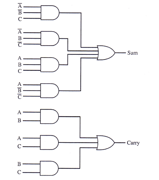
This results in the following Boolean expressions:
          Sum       = A B C + A B C + A B C + A B C


          Carry out = A B C + A B C + A B C + A B C

                    = A B C + A B C + A B C + A B C + A B C + A B C

                    = (A B C + A B C) + (A B C + A B C) + (A B C + A B C)

                    = B C + A C + A B
These expressions can be implemented with AND and OR gates as follows:
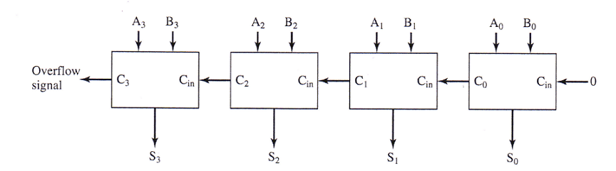
However, this only adds one bit with carrys. We need to add two n-bit numbers. We can put together a series of adders with the carry output from one being used as the input to the next.
Email Me |
Office Hours |
My Home Page |
Department Home |
MCC Home Page
© Copyright Emmi Schatz 2009